
Mechanical Differences of Wafer vs Lug Butterfly Valve Configurations in Piping Systems
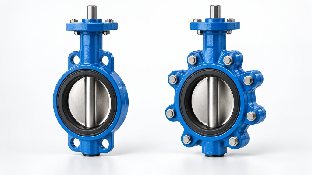
Butterfly valves are a crucial component in fluid control systems across various industries, including water treatment plants, chemical processing facilities, and HVAC systems. They are valued for their compact design, quick quarter-turn operation, simplicity, reliability, and cost-effectiveness. When it comes to selecting a butterfly valve, two common configurations are often considered: wafer and lug-style valves. The wafer vs lug butterfly valve debate centers around their distinct design and installation features, which significantly impact their performance, maintenance, and suitability for specific applications.
The primary distinction between wafer and lug butterfly valves lies in their mounting design. A wafer butterfly valve is clamped between two flanges using through-bolts, whereas a lug butterfly valve has threaded lugs that allow each flange to be bolted independently. This fundamental difference affects not only the installation process but also the valve’s functionality, pressure rating, and maintenance requirements. Understanding these differences is critical for engineers and purchasers to select the right valve for their pipeline system, ensuring optimal performance, safety, and cost-effectiveness.
The choice between wafer and lug butterfly valves depends on various factors, including the system’s operating conditions, maintenance needs, and spatial constraints. For instance, wafer butterfly valves are often preferred when compact size, lower weight, and lower
Structural Geometry: Comparing Wafer and Lug Body Profiles
The primary physical distinction when evaluating a wafer vs lug butterfly valve lies in the external geometry of the valve body and how it interfaces with adjacent piping flanges. A wafer butterfly valve features a highly compact, lightweight profile with a minimal face-to-face dimension. The body is designed to be sandwiched directly between two pipe flanges, relying entirely on the compressive force of long, continuous through-bolts or studs that span the entire width of the assembly. To facilitate installation, wafer bodies typically incorporate non-threaded alignment holes or positioning ears on the outer perimeter. These holes do not secure the valve independently; rather, they guide the bolts to ensure the disc is concentric with the pipe bore before the flanges are tightened.
In contrast, a lug butterfly valve features a more robust, heavier body design characterized by integrated, protruding lugs distributed around its outer circumference. These lugs contain factory-machined, threaded inserts. Instead of using long through-bolts to clamp the valve between flanges, the lug design utilizes shorter, independent bolts that thread directly into the valve body from both sides. This structural variation eliminates the need for a single, shared clamping assembly, allowing each flange to be bolted separately.
Key Physical Differences
| Design Parameter | Wafer Body Profile | Lug Body Profile |
|---|---|---|
| Bolt Hole Type | Non-threaded alignment holes or ears | Integrated, threaded protruding lugs |
| Body Mass & Profile | Lightweight, ultra-compact face-to-face | Heavier, robust structural casing |
| Securing Mechanism | Clamped via flange-to-flange through-bolts | Bolted independently from each flange side |
Bolting and Alignment Mechanics During Installation
When installing wafer and lug butterfly valves, understanding the bolting configuration is crucial for ensuring proper alignment, secure fastening, and minimizing potential issues during operation and maintenance. Wafer butterfly valves are clamped between two pipe flanges using long through-bolts or studs that pass through both flanges and the valve body. This design requires precise alignment of the valve between the flanges, as the bolting applies uniform pressure to secure the valve in place. The valve body itself does not have flanges or bolt holes, relying entirely on the compression provided by the surrounding flanges for sealing. This configuration can make maintenance more challenging, as removing the valve affects the entire pipeline section, and both sides of the piping must be disconnected. In contrast, lug butterfly valves feature threaded lugs around the valve body, allowing each flange to be bolted independently using shorter bolts. This design provides greater flexibility for pipeline maintenance, as one side of the pipeline can be disconnected without removing the valve from the opposite flange. The independent flange connection also enables lug valves to be used in end-of-line service, where wafer valves are not suitable due to the risk of valve body shift or leakage under pressure. Proper installation of both types requiresSealing Integrity and Operating Pressure Thresholds
When evaluating wafer and lug butterfly valves for specific applications, understanding how their design affects sealing integrity and pressure containment is crucial. The primary distinction lies in how each type is mounted to the pipeline, which influences its performance under variable pressure cycles. Wafer butterfly valves rely on the compression provided by two flanges to ensure sealing performance. They are clamped between two pipe flanges using through-bolts, creating a single clamped assembly. This design makes them compact and lightweight, suitable for applications where space is limited and cost-efficiency is a priority. However, their sealing integrity is heavily dependent on the flange’s ability to provide consistent compression. If one side of the pipeline is removed, the valve may shift or lose support, potentially leading to leakage or failure. In contrast, lug butterfly valves have threaded lugs around the valve body, allowing each flange to be bolted independently to the valve. This design provides greater flexibility for pipeline maintenance and equipment isolation, as one side of the pipeline can be disconnected without affecting the other side. The independent flange connection also enables lug valves to be used in end-of-line (EOL) service, where wafer valves are not suitable due to their reliance on bilateral support for sealing integrityDead-End Service Suitability and Downstream Isolation
The mechanical connection design of a butterfly valve directly dictates its suitability for dead-end, or terminal, piping service. A wafer butterfly valve is engineered to be sandwiched between two pipeline flanges, relying entirely on the compressive clamping force of long through-bolts that span the entire valve-to-flange assembly. Because the wafer body lacks independent mechanical anchoring to either flange, removing downstream piping for maintenance or system modification relieves this essential compression. Without dual-sided flange support, the wafer valve cannot maintain its seal, creating a severe risk of leakage, seat displacement, or catastrophic blowout under line pressure. Consequently, a wafer valve cannot be safely used for dead-end service unless a blind flange is securely bolted to its downstream side to replicate the necessary clamping force.
Conversely, a lug butterfly valve features integrated, threaded metal lugs around its perimeter. This structural difference allows short bolts to be threaded directly into the valve body from each side independently. Because the upstream and downstream connections do not share the same bolts, the downstream piping can be completely depressurized and disconnected while the valve remains securely bolted to the active upstream flange. This independent bolting mechanism enables the lug design to serve as a reliable terminal isolation point, allowing operators to isolate upstream media during downstream maintenance without shutting down the entire system.
When evaluating a wafer vs lug butterfly valve for terminal isolation, piping engineers must verify the valve’s specific dead-end pressure rating. In many industrial applications, the maximum allowable pressure for a lug valve in dead-end service is lower than its standard bi-directional rating when sandwiched between flanges. Factors such as seat retention design, media temperature, and pressure class must be cross-referenced with manufacturer specifications to ensure safe, long-term operation at the end of a piping run.
Maintenance Overheads, Operational Impact, and Cost Trade-offs
When evaluating a wafer vs lug butterfly valve for industrial facilities, water treatment, or infrastructure piping, engineers must balance initial capital expenditure (CAPEX) against long-term operational expenditure (OPEX). Wafer-type valves present a lower upfront purchase cost and a lighter, more compact footprint. However, this initial savings is often offset by higher maintenance overheads and extended system downtime during routine line servicing.
The primary driver of these lifecycle cost differences is how each design handles piping disassembly. Because a wafer valve is sandwiched between two flanges using continuous through-bolts, the valve body relies entirely on the compressive force of both flanges to maintain its seal. Consequently, performing downstream piping maintenance, cleanouts, or component replacements requires complete depressurization and draining of the entire line segment. Removing the bolts on one side releases the clamping pressure across the entire joint, meaning the valve cannot remain in service to isolate the upstream fluid.
In contrast, lug-type butterfly valves feature threaded lugs around the perimeter of the body. This allows independent bolting of the upstream and downstream flanges. During maintenance, technicians can safely disconnect and remove the downstream piping while the valve remains bolted to the upstream flange, acting as an isolation barrier. This capability prevents system-wide shutdowns and eliminates the need to depressurize the entire network. For critical applications operating under PN 10/16 pressure ratings, the ability to perform localized maintenance without interrupting upstream operations makes the higher initial cost of a lug valve highly economical over the system’s operational lifespan.
Engineering Takeaways
When selecting between wafer and lug butterfly valves, engineers should consider the piping system’s design and installation requirements. Wafer butterfly valves are suitable for applications with limited space and weight constraints, as they are compact and lightweight. However, they may require additional support to prevent damage from pipeline stress.
Lug butterfly valves, on the other hand, offer more flexibility in installation and are often preferred for applications where frequent maintenance is anticipated. Their design allows for easier removal and replacement without disrupting the entire pipeline.
It is crucial to evaluate factors such as pressure ratings, flow control needs, and environmental conditions to ensure the chosen valve type meets the system’s specifications. Proper installation and maintenance are also essential to ensure the valve’s performance and longevity.
Ultimately, a thorough understanding of the key differences between wafer and lug butterfly valves enables engineers to make informed decisions and select the most suitable valve type for their specific application.
Frequently Asked Questions
Wafer Vs Lug Butterfly Valve: What are the main differences between wafer butterfly valves and lug butterfly valves?
Wafer butterfly valves and lug butterfly valves differ primarily in their design and installation. Wafer butterfly valves are designed to be installed between two flanges in a pipeline system, relying on the pipeline’s flanges to secure the valve in place. In contrast, lug butterfly valves have threaded holes on their outer flange that allow them to be bolted directly to pipeline flanges, providing an additional layer of security and making them suitable for applications where valve removal is anticipated without disturbing the pipeline.
How do wafer and lug butterfly valves compare in terms of installation and maintenance?
In terms of installation and maintenance, lug butterfly valves offer greater flexibility and ease. Because they can be installed and removed without affecting the pipeline’s integrity, lug valves are preferred in systems where frequent maintenance or valve replacement is expected. Wafer butterfly valves, while simpler in design and generally easier to install in tight spaces, require more careful planning for maintenance, as removing them often necessitates disassembling parts of the pipeline.
Can wafer butterfly valves and lug butterfly valves be used in the same applications
Related Vahid Valves Resources
- What Is PN in Valves? Pressure Rating Explained
- What Is a Knife Valve? Applications, Design and Selection Notes
Related Vahid Valves Resources
- What Is PN in Valves? Pressure Rating Explained
- What Is a Knife Valve? Applications, Design and Selection Notes
Related Vahid Valves Resources
- What Is PN in Valves? Pressure Rating Explained
- What Is a Knife Valve? Applications, Design and Selection Notes
Related Vahid Valves Resources
- What Is PN in Valves? Pressure Rating Explained
- What Is a Knife Valve? Applications, Design and Selection Notes