
Foot Valve Spring Type PN10‑16‑25: Design and Selection Guide
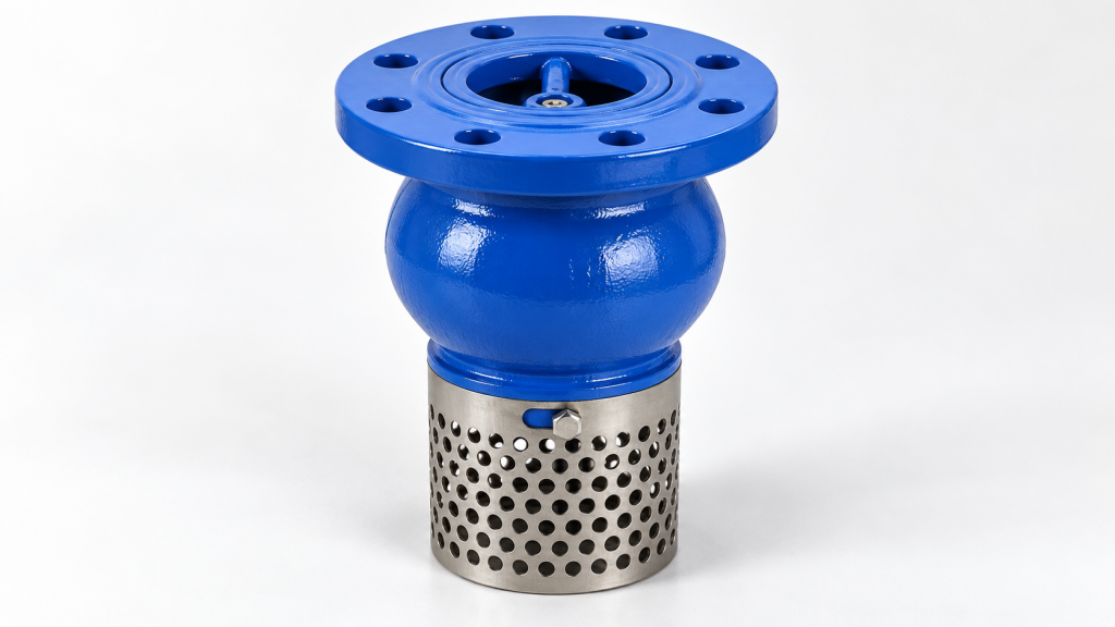
This guide examines foot valve spring type pn10-16-25 in the context of Foot Valve Spring Type PN10-16-25: Design and Selection Guide. Foot valves are critical components in pumping systems, serving as suction-side check valves that maintain prime and prevent backflow. Positioned at the lowest point of the suction line, they ensure continuous fluid flow into the pump while filtering debris through an integrated strainer. These valves are available in various designs, including spring-poppet, ball, and flapper types, each suited to specific fluid properties and operating conditions. Proper selection of a foot valve involves careful consideration of pressure ratings, material compatibility, strainer design, and hydraulic factors such as pressure drop and installation depth.
The spring-poppet design is particularly effective for its rapid closure and ability to mitigate water hammer, making it suitable for applications where quick response and damping are essential. However, the choice between spring-poppet, ball, and flapper types depends on factors such as fluid viscosity, presence of solids, and the need for low pressure drop. For instance, ball-type foot valves are often preferred for viscous fluids or slurries to avoid clogging, while flapper-type valves offer low pressure drop in large-diameter pipelines but may require additional damping to prevent water hammer.
When selecting a foot valve, engineers must also consider the pressure rating, expressed as PN classes such as PN10, PN16, and PN25, which indicate the valve’s ability to withstand specific pressure levels. The body material must be compatible with the pumped fluid to ensure corrosion resistance and long-term reliability. Additionally, the strainer design should aim for a high open-area ratio to minimize head loss, and the valve size should match the pump suction line diameter to reduce cavitation risk. Understanding these factors is crucial for ensuring the foot valve operates efficiently and reliably within the pumping system.
Fundamentals of Foot Valve Operation and Spring‑Assisted Poppet Design
A foot valve installed at the bottom of a pump suction line acts as a one‑way check valve that keeps the suction column filled when the pump stops, thereby preserving prime and preventing backflow into the source. The valve opens when pump‑generated suction reduces pressure below the inlet static head, allowing flow toward the pump, and closes automatically when the pump stops, trapping liquid in the suction pipe.
Spring‑loaded poppet mechanism
In Vahid’s spring‑type foot valve the closing element is a poppet (or wedge) that is pressed against its seat by a helical spring. When suction pressure exceeds the spring preload, the poppet lifts, opening the flow path; when pressure falls, the spring forces the poppet back onto the seat, achieving rapid shut‑off. This rapid closure reduces the chance of water‑hammer because the flow is stopped before a significant pressure wave can develop.
The internal design mirrors that of Vahid’s Spring Check Valve PN 10/16, which uses a ductile‑iron body (GJS400) with an EPDM‑encapsulated wedge and a stainless‑steel spring (1.4301). The spring seat is made of POM, providing low‑friction movement and corrosion resistance. These materials are selected for water‑based services up to 80 °C and are protected by an epoxy powder coating.
| Component | Material (Vahid Spring Check Valve) |
|---|---|
| Body | Ductile iron GJS400 (EN 1563) |
| Wedge | GJS400 encapsulated with vulcanized EPDM |
| Spring | Stainless steel 1.4301 |
| Spring seat | POM |
| Coating | Epoxy powder |
Because the poppet is spring‑actuated, the valve exhibits a low cracking pressure (typically ≈0.1 bar to open) and a higher reseating pressure (≈0.5 bar) that helps maintain a sealed column without excessive spring force that could impede pump start‑up.
Proper installation requires submerging the valve at least four to five times the pipe diameter to avoid drawing silt or forming surface vortices, and aligning the flow‑direction arrow on the body with the suction line. The integral strainer commonly incorporated in foot‑type designs filters debris, protecting the pump impeller and reducing maintenance frequency.
Vahid backs the Foot Valve Spring Type PN10‑16‑25 with a 5‑year guarantee and 25‑year after‑sale service, supporting long‑term reliability in pumping stations, irrigation, and water‑supply applications.
Pressure Ratings PN10, PN16, PN25: Meaning, Standards and Testing
The PN designation (Pression Nominale) is a European‑based pressure class that indicates the maximum allowable working pressure of a valve at reference temperature, expressed in bar. For water‑based systems at 20 °C, PN10 corresponds to 10 bar (≈145 psi), PN16 to 16 bar (≈232 psi) and PN25 to 25 bar (≈363 psi). These values are derived from the nominal pressure multiplied by a safety factor defined in the relevant standards.
When selecting a foot valve, the PN rating must exceed the highest expected system pressure, including surge conditions, to avoid permanent deformation or leakage. Vahid Valves lists a Foot Valve Spring Type PN10‑16‑25, meaning the same model can be supplied in any of those three pressure classes; the choice depends on the design pressure of the suction line.
Testing of PN‑rated valves follows internationally recognised procedures. Hydrostatic shell and seat tests are prescribed in EN 12266‑1 and EN 12266‑2, while API 598 provides the acceptance criteria for leak rates. Flange dimensions and bolt patterns are governed by ANSI B16.5 (or its metric equivalent EN 1092‑2), and the overall design may reference ASME B16.34 or BS EN 12516 for pressure‑temperature ratings.
| PN class | Working pressure (bar) | Approx. psi | Typical ANSI flange class |
|---|---|---|---|
| PN10 | 10 | 145 | 150 |
| PN16 | 16 | 232 | 150 |
| PN25 | 25 | 363 | 300 |
Using the table, engineers can quickly match a required system pressure to the appropriate PN rating and verify that the selected foot valve complies with the applicable test standards.
Body Material Selection for Corrosion Resistance and Fluid Compatibility
Choosing the body material for a foot valve spring type PN10‑16‑25 means matching alloy or polymer to fluid chemistry, temperature, and pressure. Typical options are brass, bronze, stainless steel, ductile or cast iron, carbon steel, and PVC/PP.
Brass and Bronze
Brass resists fresh water and mild alkalis, suited to irrigation and low‑temperature water service. Bronze’s higher tin content improves seawater tolerance, making it preferable for marine or coastal installations.
Stainless Steel
Austenitic grades such as 1.4301 (304) resist acids, bases, and chlorinated waters. They are selected for aggressive chemicals or higher temperatures where brass or bronze may lose strength.
Ductile and Cast Iron
Ductile iron (GJS400) provides high strength and toughness; epoxy coating lets it handle potable water, wastewater, and non‑corrosive fluids up to PN10‑16‑25. Plain cast iron is less impact‑tolerant but usable in low‑pressure, non‑abrasive services where cost matters.
Carbon Steel
Carbon steel is strong and economical but needs internal linings (epoxy, rubber) or external coatings to avoid rust in water or weakly aggressive fluids. It appears in treated‑water industrial plants.
Thermoplastics (PVC/PP)
PVC and polypropylene resist acids, alkalis, and salts at ambient temperature. Their use is limited to lower pressure classes (typically PN10 or PN16) and temperatures below the material’s softening point, suiting chemical dosing, seawater intake, or corrosive effluent lines.
Always confirm that the material’s pressure‑temperature rating meets the required PN and that any linings or coatings are compatible with the fluid and site conditions.
Strainer Design: Open‑Area Ratio, Screening Efficiency and Head Loss Minimization
The integral strainer in a foot valve blocks debris before it reaches the pump impeller, check valve mechanism and downstream piping, preserving hydraulic efficiency and extending service life.
Design guidelines call for the strainer’s open area to be three to four times the pipe’s cross‑sectional area (open‑area‑to‑pipe‑area ratio of 3:1–4:1). This range provides adequate particle retention while keeping the added pressure drop low enough not to erode the pump’s available net positive suction head (NPSHa).
Mesh selection trades off particle size against flow resistance. A finer mesh captures smaller solids but reduces open area, raising head loss; a coarser mesh preserves open area but may allow larger particles to pass. For clean water a mesh opening of 0.5 mm to 1.0 mm is typical, whereas wastewater or slurry service often uses a larger opening or a perforated plate to avoid blinding.
Strainer geometry affects flow distribution. A tapered inlet can accelerate velocity toward the screen centre, increasing local head loss if the open area is insufficient. A wide, low‑profile strainer with a large surface area promotes even flow and minimizes turbulence‑induced losses. Maintaining the recommended open‑area ratio helps preserve NPSHa and reduces cavitation risk.
When selecting a foot valve, verify that the strainer’s open area meets the 3:1–4:1 guideline for the intended pipe size and that the mesh matches the expected solids concentration. This approach balances debris protection with suction performance.
Hydraulic Considerations: Pressure Drop, NPSHa, Cavitation and Installation Depth
When selecting a foot valve for a suction line, the first hydraulic check is the pressure loss across the valve at the expected flow rate. The loss can be estimated from the valve’s flow coefficient (Cv or Kv) supplied by the manufacturer; for Vahid’s Foot Valve Spring Type PN10‑16‑25 the Kv value is listed in the product data sheet and should be used in the Darcy‑Weisbach or Hazen‑Williams equation to compute head loss. Keeping this loss low preserves the available net positive suction head (NPSHa) and reduces the risk of cavitation at the pump impeller. This factor should also be verified when evaluating foot valve spring type pn10-16-25.
NPSHa is calculated as the absolute pressure at the suction flange minus the vapour pressure of the fluid, minus the suction‑line losses (including the foot valve) and the velocity head. A conservative design target is to maintain NPSHa at least 0.5 m above the pump’s required NPSHr. If the estimated pressure drop from the foot valve consumes a large portion of the available head, either increase the valve size (matching the suction line diameter) or select a model with a higher Kv.
To avoid vortex formation and silt ingestion, the valve should be submerged to a depth of four to five times the pipe diameter. This rule of thumb applies regardless of material or pressure rating and helps keep the inlet flow uniform and free of entrained air.
| Pipe DN (mm) | Recommended submergence depth (mm) |
|---|---|
| 50 | 200 – 250 |
| 80 | 320 – 400 |
| 100 | 400 – 500 |
| 150 | 600 – 750 |
| 200 | 800 – 1000 |
Matching the foot valve nominal size to the suction line diameter minimises additional turbulence and helps maintain sufficient NPSHa. For the Vahid Foot Valve Spring Type PN10‑16‑25, consult the manufacturer’s Kv curve and installation manual to verify that the selected size meets both the pressure‑drop and submergence criteria for your specific pumping system.
Foot Valve Spring Type Pn10-16-25: Comparison with Ball‑Type and Flapper‑Type Foot Valves: When Spring‑Poppet Is Preferred
Spring‑poppet foot valves employ a spring‑loaded disc that opens when suction pressure exceeds the cracking pressure and closes rapidly when the pump stops. The spring provides a cushioned shut‑off that can help limit water‑hammer, while the poppet presents a smaller flow area than a full‑port flapper.
| Attribute | Spring‑Poppet | Ball‑Type | Flapper‑Type |
|---|---|---|---|
| Clogging resistance | Moderate – poppet may trap fines | High – ball rolls past debris | Low‑moderate – hinge can collect fibers |
| Pressure drop | Higher than flapper | Similar to spring‑poppet | Lowest – full port |
| Water‑hammer tendency | Lower – spring cushions closure | Moderate – depends on velocity | Higher – heavy flapper may slam |
| Preferred fluid | Clean water, low viscosity | Viscous fluids, slurries | Large‑diameter clean water |
Proper installation requires submerging the valve at least four to five pipe diameters below the reservoir surface to avoid silt intake and surface vortices. The integral strainer, common to all foot‑valve types, should be sized for a high open‑area‑to‑pipe‑area ratio to keep head loss acceptable while protecting downstream equipment.
For clean‑water pumping stations where rapid shut‑off and minimal water‑hammer are priorities, a spring‑poppet foot valve offers a reliable solution. When the suction line carries slurries, high‑viscosity liquids, or solids that could jam a poppet, a ball‑type foot valve is often the safer choice, while flapper types suit large‑diameter low‑loss applications.
Vahid’s spring‑poppet foot valve (PN10‑16‑25) is supplied with a ductile‑iron body and epoxy powder coating, consistent with the material specification of its spring check valve range.
Maintenance, Inspection and Lifecycle Reliability: Ensuring Long‑Term Performance
For a foot valve installed on a pump suction line, routine upkeep preserves priming capability, prevents premature wear, and maintains the hydraulic integrity of the system.
Recommended maintenance intervals
- Strainer screen: inspect and clean every 3–6 months, or sooner if pressure drop increases.
- Seal and seating surfaces: visual check for wear, scoring, or deformation during each strainer cleaning.
- Spring assembly: verify free movement and correct tension annually; replace if signs of fatigue or corrosion appear.
- Body and flange surfaces: check for external corrosion or coating damage at least once a year, especially in aggressive or saline environments.
These actions keep the integral strainer from clogging, ensure the poppet seals tightly, and confirm that the spring‑assisted closure remains responsive.
Record‑keeping and functional testing
- Log each inspection date, observed condition, and any corrective action.
- Perform a manual lift test of the poppet after reassembly to confirm free movement and proper seating.
- Verify that the strainer reinstalled does not obstruct flow by measuring pressure differential before and after cleaning if possible.
Vahid Valves backs the Foot Valve Spring Type PN10‑16‑25 with a five‑year guarantee and a twenty‑five‑year after‑sale service programme. The guarantee covers material and workmanship defects under normal service conditions, while the long‑term service provides spare‑part availability, technical support, and optional on‑site inspection throughout the valve’s expected lifespan. This combination allows planners to schedule maintenance with confidence that replacement components and expert assistance will be accessible for the duration of the installation.
Engineering Takeaways
The selection of a spring‑type foot valve in the PN10‑16‑25 range begins with confirming that the valve’s pressure class matches the maximum suction‑side pressure expected in the system, while also verifying that the body material is compatible with the pumped fluid to avoid corrosion or degradation. For clean water or low‑viscosity liquids, the spring‑poppet design offers fast closure and helps limit water‑hammer effects; however, when the fluid contains solids, slurries, or high viscosity, a ball‑type or flapper configuration may be preferable to reduce clogging risk. The integral strainer should provide an open‑area‑to‑pipe‑area ratio of at least 3:1 to keep head loss low, and the valve must be sized to the pump suction line diameter to maintain adequate NPSHa and minimize cavitation. Installation depth of four to five pipe diameters below the liquid surface prevents silt ingestion and surface vortex formation, and the flow‑direction arrow must be observed. Regular maintenance—strainer cleaning, seal inspection, spring tension check, and corrosion assessment—ensures long‑term reliability. Vahid Valves lists a Foot Valve Spring Type PN10‑16‑25 in its catalog and backs it with a five‑year guarantee and a 25‑year after‑sale service period.
Frequently Asked Questions
What is a foot valve spring type and how does it function?
A foot valve spring type is a suction‑side check valve installed at the bottom of a pump suction line. It uses a spring‑loaded poppet that opens when pump suction creates enough pressure and closes rapidly when flow stops, thereby maintaining pump prime and preventing backflow. Many designs also incorporate an integral strainer to filter debris and protect downstream equipment.
What pressure ratings are available for the Vahid Foot Valve Spring Type PN10‑16‑25?
The designation PN10‑16‑25 indicates that the valve is manufactured to meet PN10, PN16, and PN25 pressure classes (approximately 10 bar, 16 bar, and 25 bar). These ratings allow the valve to be used in systems where the maximum operating pressure does not exceed the selected class, in line with general industry practice for foot valves.
How should the valve be installed to ensure proper performance?
Install the foot valve at the lowest point of the pump suction line (the “foot”). Submerge it to a depth of at least 4–5 times the pipe diameter to avoid drawing silt or forming surface vortices. Observe the flow‑direction arrow on the body, match the valve nominal size to the pump suction line diameter, and use the appropriate connection type (threaded, socket, or flange) that matches the piping system.
What maintenance is recommended and what warranty does Vahid provide?
Routine maintenance includes periodically removing and cleaning the integral strainer, inspecting the sealing surfaces (seat and poppet) for wear, verifying spring operation and tension, and checking for corrosion or degradation of the body. Worn components such as seals or springs should be replaced per the manufacturer’s recommendations. Vahid Valves backs the Foot Valve Spring Type PN10‑16‑25 with a 5‑year guarantee and offers 25‑year after‑sale service.
Related Vahid Valves Resources
- What Is PN in Valves? Pressure Rating Explained
- Foot Valve Ball Type PN10-16-25
- Spring Check Valve PN 10/16
Technical References
- Foot Valve: Essential Guide for Plumbing Success | Kentucky Plumbing
- What is a Foot Valve? Working, Types & Foot Valve vs Check Valve (2026) – EPCLand
- Foot Valves PN10-16-25-40 – Global Flow ControlPN10, PN16, PN25 Ball Valves: Understanding Pressure Ratings -Foot Valves PN10-16 – Global Flow ControlComprehensive Valve Standards List | PDF | Valve | Pipe …Valve Standards: API, ANSI, ISO, and PN Explained | GangyeValve Standards | Industrial Valve Engineering Knowledge …Industrial Valve Standards Overview | PDF | Valve … – Scribd
- Spring Foot Valve