
Engineering Pipeline Collapse Prevention: Sizing and Placing Air Inlet Valves
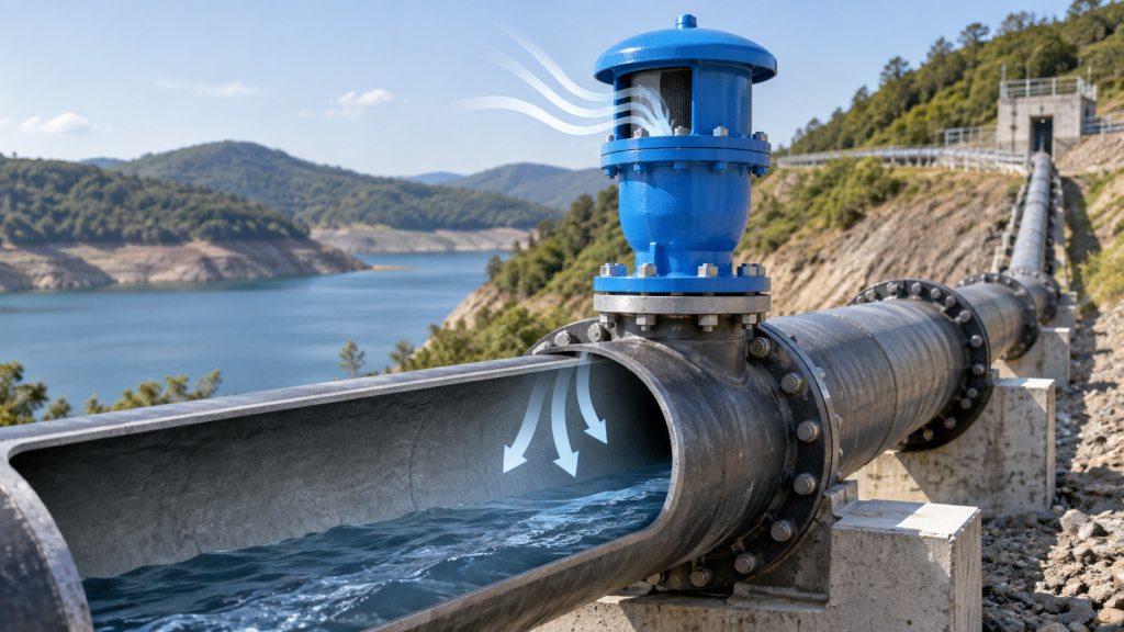
Pipeline collapse due to vacuum formation remains one of the most insidious yet preventable failures in pressurized fluid transport systems. Unlike overpressure events, which generate visible distress or alarms, vacuum conditions develop silently—until the pipeline wall buckles inward under atmospheric differential pressure, often with catastrophic consequences. The root cause lies in air exclusion: when liquid flow ceases or reverses, entrapped air cannot escape, creating low-pressure zones that collapse the pipe like an empty soda can. Field data confirms that improper air inlet service is a leading contributor to these failures, surpassing mechanical or material defects in pipeline forensics studies. The challenge lies in balancing air admission with flow continuity; valves must admit air only when necessary to prevent vacuum while avoiding air binding that disrupts hydraulic efficiency.
Engineering solutions must address both the physics of vacuum formation and the operational constraints of pipeline drainage. Air inlet valves serve a dual role: they must admit atmospheric pressure during shutdown or reverse flow to prevent collapse, yet avoid introducing excessive air that disrupts system efficiency or triggers surge events during re-pressurization. The misconception that air management is secondary to pressure control persists, yet industry records show that vacuum-induced collapses account for 30–40% of pipeline failures during drainage or emergency shutdowns. Strategic valve placement, sizing, and valve type selection—ranging from simple vacuum breakers to combination air/vacuum units—become critical to mitigating this risk while maintaining operational reliability. The interplay between valve function, pipeline profile, and operational protocols demands systematic analysis to avoid both under- and over-specification.
The Physics of Vacuum Formation and Pipeline Collapse
Pipeline structural integrity is heavily dependent on maintaining positive internal pressure. When internal pressure drops below atmospheric pressure, a vacuum state is created. In large-diameter or thin-walled pipelines, the external atmospheric pressure exerts a massive compressive force on the pipe walls. If the pipe’s structural stiffness is insufficient to counteract this external load, the result is rapid buckling or catastrophic structural collapse.
Several transient hydraulic events can trigger these dangerous negative pressure conditions:
- Rapid Draining: During the emptying of a pipeline, if air is not admitted at a rate sufficient to replace the departing liquid, a vacuum forms. This is particularly critical in long ascents or during sudden discharge events.
- Pump Failures and Power Outages: A sudden loss of power to pumps can cause a rapid change in flow velocity. This momentum shift can lead to column separation, where the liquid column breaks, creating localized vacuum pockets.
- Mechanical Air Entrainment: While air is often a nuisance at high points, its role in vacuum formation is a matter of mass balance. Under vacuum conditions, air is actively drawn into the system through mechanical equipment, such as pump packing or valve seals, which can exacerbate the pressure drop.
The severity of the risk is influenced by the pipeline’s hydraulic profile. For instance, long horizontal runs and steep ascents are particularly susceptible to vacuum formation during draining or sudden flow changes. To prevent collapse, the system must be capable of admitting air rapidly enough to equalize the internal and external pressures before the pipe reaches its critical buckling limit.
Mechanics of Air/Vacuum and Combination Valves in Inlet Service
Air/vacuum and combination valves are critical for preventing pipeline collapse by managing negative differential pressure during drainage or power failures. Their operation relies on two distinct but complementary mechanisms: rapid air admission and controlled air release. During pipeline startup, the system is filled with air, which must be displaced by water. As water enters, it pushes trapped air toward high points in the line. Air/vacuum valves admit large volumes of air through a large orifice, allowing the water to displace it efficiently. This process is governed by buoyancy principles—air, being 800 times less dense than water, naturally rises and accumulates at high points, where the valve’s float mechanism remains open until the water level reaches the valve chamber.
Once the pipeline is filled, the valve’s float rises and seals the orifice to prevent fluid leakage. However, air continues to enter the system through dissolved gases, mechanical equipment, or vacuum conditions. Under normal operation, small air pockets form at high points and accumulate until the water level drops, causing the float to lower and release air through a smaller orifice. This continuous air release prevents air binding, which can drastically reduce hydraulic efficiency and increase pumping costs by up to 15%.
Combination valves integrate both air/vacuum and air release functions into a single unit, ensuring comprehensive protection. Their design includes a large port for rapid air admission during filling or vacuum conditions and a smaller orifice for continuous air release during operation. This dual functionality eliminates the need for separate valves, simplifying installation and maintenance while maintaining system reliability. The dynamic design of these valves also includes features like slow-closing mechanisms to mitigate water hammer and throttling devices to control surges, further enhancing their protective role. Proper sizing and placement—based on hydraulic conditions rather than nominal pipe diameter—are essential to prevent vacuum formation and ensure optimal performance.
Engineering Calculations: Sizing Air Inlet Valves for Collapse Prevention
To safeguard a pipeline against structural failure during rapid draining, line breaks, or column separation, engineers must calculate the pipeline’s critical buckling pressure (Pc). This value represents the maximum external pressure differential the pipe shell can withstand before collapsing. Based on Timoshenko’s structural mechanics equations and guidelines in standards such as AWWA M11, the critical collapse pressure for a thin-walled cylindrical pipe under uniform external pressure is determined by the material’s modulus of elasticity (E), Poisson’s ratio (μ), and the wall thickness-to-diameter ratio (t/D):
Pc = [2E / (1 – μ2)] × (t / D)3
In practice, a safety factor (typically 2.0 or greater) is applied to Pc to establish the maximum allowable negative pressure differential (ΔPall) inside the pipeline. The air inlet valve must be sized to ensure that the internal vacuum pressure never drops below this safe threshold.
The required volumetric air inflow rate (Qa) is directly governed by the maximum potential liquid drainage rate (Qw) under gravity or pump-out conditions. To prevent vacuum formation, the incoming air volume must replace the exiting liquid volume. This relationship is calculated at the maximum allowable pressure differential, accounting for air density changes at the design vacuum level. The required air flow rate is expressed as:
Qa = Qw × C
where C is a compression factor adjusting for the pressure differential across the valve orifice.
Once Qa and ΔPall are determined, engineers select the appropriate valve size using manufacturer intake capacity curves. For example, when specifying a combination air valve, such as the Vahid PN 10/16 designed to DIN 1074-P4, the valve’s intake capacity at the calculated ΔPall must equal or exceed the required Qa. While these ductile iron (GJS400) valves feature dynamic designs that allow high-velocity air discharge up to 0.8 bar differential pressure, their sizing for vacuum protection specifically ensures that the intake pressure drop remains safely below the pipeline’s critical buckling limit.
Strategic Location Planning along the Pipeline Profile
Strategic placement of air valves follows the pipeline’s hydraulic profile rather than mere topography. At true high points where air accumulates, a combination air valve—such as the Vahid PN 10/16 model manufactured to DIN 1074‑P4 with a ductile‑iron GJS400 body, polymer float and EN 1092‑P2 flanged connections—can both admit large volumes of air during draining and release small amounts during normal operation, thereby reducing the total number of valves required. Along long horizontal runs, dedicated air release valves handle the continuous venting of entrained air, while on sustained ascents air/vacuum valves protect against vacuum formation.
Sizing of these valves is based on the maximum expected air‑inflow rate needed to prevent vacuum, not on nominal pipe diameter, and must ensure that the pressure drop across the valve stays below the pipe’s collapse limit and any applicable differential‑pressure design criteria. Air release valves are sized empirically from operating pressure, flow rate and manufacturer performance data to avoid chronic air binding or excessive leakage.
Managing Re-Pressurization: Preventing Secondary Surges during Air Exhaust
When water columns rejoin after being separated by air pockets, the sudden collapse of the air pocket can generate a secondary surge, or water hammer, that is often more severe than the initial event. This phenomenon occurs because the water column accelerates rapidly as the air pocket is evacuated, creating a pressure wave that propagates through the pipeline. To mitigate this risk, engineers must carefully manage the air exhaust process to prevent uncontrolled re-pressurization.
One effective strategy involves the use of dual-acting, combination, or slow-closing air valves. These valves are designed to regulate the release of air from the pipeline, ensuring that the re-pressurization occurs gradually and predictably. Dual-acting valves, for example, can both admit and release air, providing a more dynamic response to changes in system pressure. Combination valves, on the other hand, integrate multiple functions into a single unit, allowing for precise control over air intake and exhaust. Slow-closing valves, as the name suggests, close gradually rather than abruptly, which helps to dampen the pressure waves generated during the re-pressurization process.
The key to preventing secondary surges lies in the careful selection and placement of these valves. They should be installed at strategic points in the pipeline, such as at high points where air pockets are most likely to form. By controlling the rate at which air is released, these valves help to minimize the risk of water hammer and other pressure-related issues. Additionally, the use of slow-closing valves can further reduce the severity of the pressure waves, providing an additional layer of protection for the pipeline and its components.
In summary, the hazards of uncontrolled air exhaust during the re-pressurization of water columns can be mitigated through the use of dual-acting, combination, or slow-closing air valves. These valves regulate the release of air, preventing secondary surges and water hammer events. By carefully selecting and placing these valves, engineers can ensure the safe and efficient operation of their pipelines, minimizing the risk of damage and downtime.
Operational Considerations: Environmental Hazards and Maintenance Protocols
Air inlet and combination air valves are continuously exposed to environmental and operational hazards that can compromise their protective functions. Debris accumulation, such as airborne dust or suspended solids in the media, can obstruct the valve orifice or cause dynamic seat sticking. In cold climates, freezing of trapped liquid inside the valve body can immobilize the float, rendering vacuum protection useless during sudden draining or power failures. Additionally, chemical attack from corrosive atmospheres or aggressive fluids can degrade standard elastomeric seals. To mitigate these risks, the Vahid Combination Air Valve PN 10/16 utilizes a high-strength, anti-sediment polymer float and an automatic plastic screen basket that prevents contact between the float and the ductile iron GJS400 casting, ensuring smooth, reliable operation.
To guarantee absolute reliability against pipeline collapse, a strict maintenance and inspection protocol must be enforced. Standard operating procedures require dismantling and cleaning mobile components to remove sediments and replacing any worn parts after three years of service. However, in systems conveying suspended particles, operating under high differential pressures, or experiencing low output rates, these intervals must be shortened to prevent premature failure.
| Operational Condition | Maintenance Protocol | Recommended Interval |
|---|---|---|
| Standard Water Systems (Max 80°C) | Clean strainers in steering or pilot circuits | Every 4 months |
| Standard Water Systems (Max 80°C) | Dismantle mobile components, clean sediments, and replace worn parts | Every 3 years |
| High Suspended Solids / High Differential Pressure | Accelerated inspection, sediment cleaning, and seal evaluation | Shortened intervals (as required) |
Engineering Takeaways
Mitigating vacuum-induced pipeline collapse requires the strategic integration of air inlet and vacuum relief valves at critical locations, including high points, abrupt grade changes, and long horizontal runs. Engineers must base valve sizing on the maximum calculated volumetric drainage rate or transient flow analysis rather than nominal pipe size alone. This analytical approach ensures that the air inflow rate can match or exceed the liquid displacement rate, maintaining internal pressure safely above the critical collapse threshold of the specific pipe material and wall thickness.
Practical implementation demands strict attention to environmental and operational hazards. Air inlets must remain completely unobstructed by debris, ice, or surrounding structures to guarantee immediate response during transient events. Furthermore, because rapid air expulsion can induce secondary pressure surges, or water hammer, during column rejoining, system designers should carefully evaluate the transition from air admission to controlled air release. Regular, documented inspection schedules are essential to verify seal integrity and prevent mechanical sticking, particularly in systems subject to particulate accumulation or extreme operating temperatures.
Frequently Asked Questions
What is air inlet service and why does it matter for pipeline integrity?
Air inlet service allows atmospheric air to enter a pipeline when internal pressure drops, preventing a vacuum that can cause the pipe wall to buckle or collapse. The Combination Air Valve PN 10/16 is designed for this function, admitting air during draining or transient low‑pressure events and releasing air during filling, thus protecting the line from collapse.
How does a combination air valve prevent vacuum‑induced collapse?
When pressure falls below atmospheric, the valve’s float drops, opening the inlet port and admitting air. The valve’s dynamic design permits high‑velocity air discharge up to 0.8 bar differential pressure, which prevents premature closing and ensures sufficient air inflow to equalize pressure. This rapid response stops vacuum formation that could lead to pipeline collapse.
What factors should guide the selection of an air inlet valve for water or non‑corrosive fluid systems?
Select a valve rated for the system’s pressure and temperature. The Combination Air Valve PN 10/16 suits water lines and non‑corrosive liquids up to 80 °C, with a working pressure range of 0.3–16 bar. Its body is ductile iron GJS400, flange follows EN 1092‑P2 (DIN 2501), and it can be epoxy or polyester coated. These attributes ensure reliable air handling and minimal maintenance.
What maintenance practices help the air inlet valve continue to protect against collapse?
The valve is engineered for minimal maintenance over its service life. Periodic inspection of the screen basket and float for sediment buildup is advisable to keep the air passage clear. Following the manufacturer’s guidance—cleaning strainers every few months and checking mobile components every few years—helps sustain reliable operation and prevents conditions that could lead to vacuum formation.
What installation practices support effective air inlet service?
Install the valve with its flange oriented per EN 1092‑P2 (DIN 2501) and ensure the pipeline is rated for the valve’s 0.3–16 bar working pressure. The valve should be positioned at high points where air can accumulate, allowing it to vent during filling and admit air during draining. Proper alignment and support prevent stress on the ductile iron body and maintain the float’s free movement.
Technical References
- Air Relief Valve: Engineering Guide to Surge Protection 2026 – EPCLand
- Air Valve Sizing & Location For Surge Control | Aquestia
- PDF Air In Pipelines
- PDF Air In Pipelines: A Technical White Paper by Val‐Matic Valve & Mfg. Corp.
- Air Release, Air/Vacuum, and Combination Air Valves: Best Practices for …