
Understanding the Three Functions of Combination Air Valves
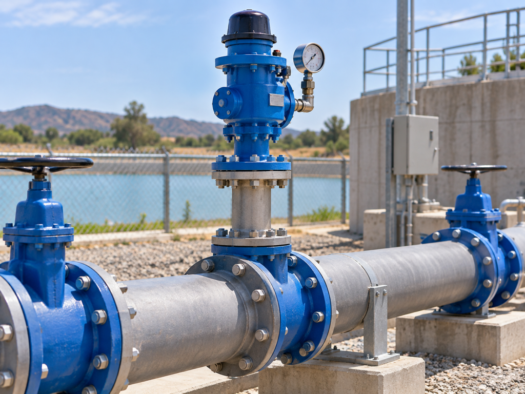
Air management is a critical discipline in the design and operation of pressurized liquid pipelines. Uncontrolled air pockets compromise conveyance efficiency, cause severe pressure surges, and accelerate localized corrosion. While single-function valves address specific localized air issues, combination air valves integrate multiple operational modes into a single, cohesive unit. This article examines the mechanical functions, selection parameters, and operational design principles governing these devices.
The Three Core Functions Explained
A combination air valve derives its designation from its capacity to handle air under three distinct hydraulic states: system filling, pressurized operation, and system drainage. Each function relies on distinct internal components responding dynamically to internal pressure and fluid levels.
1. Large-Volume Air Exhaust (Filling Mode)
During initial pipeline filling or restart after maintenance, hundreds or thousands of cubic meters of air must be expelled rapidly to prevent restriction. A combination air valve incorporates a large-orifice mechanism equipped with a buoyant float. As water enters the valve chamber, air escapes freely through the large aperture. The rising liquid level eventually lifts the float against the sealing seat, closing the large orifice to prevent liquid discharge once the system is fully primed.
2. Continuous Micro-Venting (Pressurized Operation)
Water under pressure continuously releases dissolved gases. As these microscopic bubbles migrate to pipeline high points, they coalesce into larger pockets that reduce effective cross-sectional flow area and restrict hydraulic performance. In response, the valve’s automatic small-orifice mechanism remains functional while the pipeline is pressurized. Small volumes of accumulated air displace the water level within the lower-capacity mechanism, allowing the air to vent continuously without requiring system depressurization.
3. Vacuum Breaking and Air Intake (Draining Mode)
When a pipeline is drained intentionally for maintenance, or rapidly emptied due to pump failure or pipe burst, internal pressure drops below atmospheric levels. Without adequate air admission, a severe vacuum can form, leading to pipeline buckling, wall collapse, or cavitation damage. During drainage events, the internal water level drops, causing the floats to descend and reopen the large orifice. Ambient air rushes into the pipeline, neutralizing negative pressure differentials and maintaining structural integrity.
Engineering and Construction Specifications
Selecting an appropriate air valve requires strict adherence to operating parameters and material compatibility. For standard water and non-corrosive liquid applications operating up to an 80°C maximum temperature, structural integrity is paramount.
Taking Vahid’s manufacturing standards as a benchmark, industrial combination air valves are engineered in compliance with specifications such as DIN 1074–P4. Working pressures typically span a range of 0.3 to 16 bar (4 to 230 psi), accommodating standard PN 10/16 piping networks. Bodies and caps are predominantly cast from ductile iron, specifically GJS400 EN 1563 (DIN 1693), providing robust resistance against mechanical stress. Internal floats utilize high-strength, anti-sediment polymers, complemented by soft rubber coatings on automatic floats to guarantee sealing performance at lower operating pressures. Flange connections conform to standards such as EN 1092-P2 (DIN 2501).
| Operational Mode | Primary Mechanism | Hydraulic Objective |
|---|---|---|
| System Filling | Large Orifice / Large Float | High-velocity discharge of large air volumes |
| Pressurized Run | Small Orifice / Automatic Float | Continuous venting of accumulated dissolved gases |
| System Drainage | Large Orifice Descent | Vacuum breaking via rapid ambient air intake |
Strategic Placement and Installation Considerations
Proper positioning dictates the efficacy of any air management strategy. Engineers must locate combination air valves at specific network high points, changes in vertical alignment, long horizontal runs with minimal grade, and immediately downstream of pump discharge headers where air entrainment is most pronounced.
In outdoor installations, exposure to direct sunlight and thermal cycling should be mitigated through protective coatings, such as UV-resistant polyester finishes applied over epoxy powder bases. In cold climates, installation depth relative to the local frost line or placement within insulated valve chambers prevents ice blockages from disabling the valve’s discharge capability.
Maintenance Best Practices
While modern combination air valves are designed for minimal intervention throughout their operational lifecycle, periodic inspections remain necessary. Mineral scaling, suspended solids, and biological growth can accumulate on floats, impairing buoyancy and causing weeping or leakage across the seal.
Routine checks should verify the free movement of internal components and inspect plastic screen baskets—such as those integrated into Vahid automatic valve designs to prevent float-to-casting contact. Additionally, ensure that isolation valves installed beneath the air valve remain fully open and accessible for emergency maintenance.
Technical References
- AWWA M51: Air-Release, Air/Vacuum, and Combination Air Valves
- DIN 1074-P4: Valves for Water Supply Service
- EN 1092-P2: Flanges and their joints – Circular flanges for pipes, valves, fittings and accessories
Frequently Asked Questions
Why is a combination air valve preferred over separate air-release and air/vacuum valves?
A combination air valve integrates the functions of both devices into a single housing, reducing installation footprint, lowering procurement costs, and simplifying maintenance routines by eliminating the need for separate tapping points on the pipeline.
What causes premature closure of an air valve during system filling?
Premature closure occurs when high-velocity air rushing through the large orifice creates a low-pressure area (Venturi effect) that prematurely lifts the float before all air is evacuated. Advanced dynamic designs mitigate this by allowing high-velocity air discharge up to 0.8 bar differential pressure.
Can combination air valves handle corrosive industrial fluids?
Standard municipal configurations utilize ductile iron bodies with epoxy or polyester coatings suitable for non-corrosive liquids up to 80°C. For aggressive chemical or slurry applications, material specifications must be verified against dedicated chemical resistance charts.